Waukesha L5792D Top End Overhaul
Read more on how we helped this client below and discover how we can help you too...

Background
Bartech was invited to attend the offshore Platform to conduct a top-end overhaul of the Waukesha L5792D Emergency Generator “A” following extensive damage found to the rocker arms, pushrods and suspected damage to the camshaft during a previous health check visit by Bartech.
Prior to our arrival on the platform and in order to save some time the rig engineers had removed the inlet manifolds, air filters, fuel pipes and cylinder heads. Upon closer inspection, the removal of the cylinder heads with the rocker gear and pushrods still attached had placed severe tension on the component parts which we believe may have led to the cracking of 6 x cylinder heads and 3 x rocker posts, bending of several push rods and numerous cylinder head studs. This had no detrimental effect on the overhaul but will have negative consequences if the heads were planned to be refurbished and reused in the future.

Solution
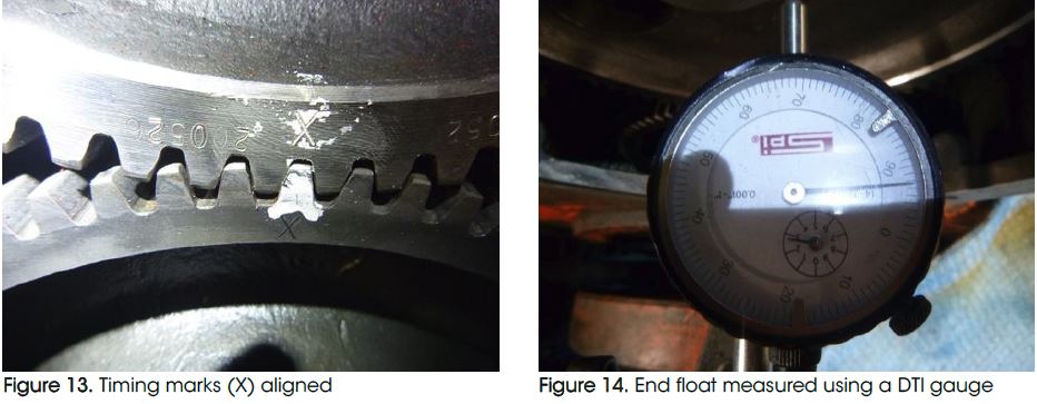
The dismantling of the engine continued. This involved the removal of all temperature and pressure probes, coolant and oil delivery pipework and lifting clear the coolant/exhaust manifold allowing it to be dismantled and cleaned. The coolant pump was removed allowing access to the camshaft timing gears. The timing marks were aligned and the camshaft end float and backlash measured for future reference (the end float was found to be outside of the manufacturer’s maximum tolerance by 0.003”, this will be rectified during the rebuild phase). The timing gear was hydraulically pulled from the camshaft allowing the camshaft covers to be lifted and the camshaft to be removed from the engine saddle.
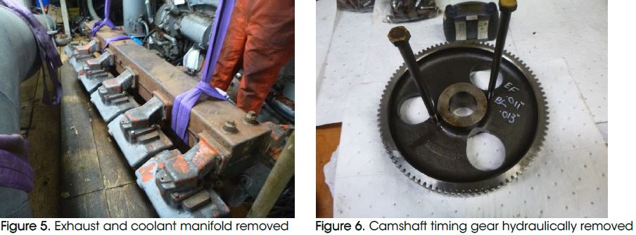
A visual inspection was conducted of all engine components and damage was found on several followers, camshaft lobe profiles and camshaft shell bearings. The damage sustained was consistent with that expected from the rocker gear adjusters breaking up and entering the lubrication system. With the camshaft removed the camshaft trough and engine saddle was comprehensively cleaned to remove any residual dirt or foreign material.
To confirm that the particles found in the camshaft area had not caused damage to the crankshaft or big ends, it was decided to remove the big end bearing caps on pistons on
the right bank 1, 3 and 4. These were removed, and a visual inspection conducted. No scoring or damage was observed on the crankpins and only minor wear was evident on
the bearings. The white metal bearing surfaces were still intact and there were no signs of ingress of foreign materials with only the normal wear patterns expected from an engine of its age.
The bearings were cleaned, lubricated and installed in their respective positions and the manufacturers recommended procedure followed to correctly install, torque and check
them in position.
All component parts were cleaned to remove old residue gasket material, O-rings, general dirt and carbon deposits. The cylinder bores and fuel injection pump delivery valves were thoroughly cleaned to remove any particles that may have entered during the rig engineer’s dismantling process. These were then covered to prevent future ingress of
debris during the rebuild process. Focus on cleaning mainly concentrated on those items that had been left open to the elements during the dismantling process by the platform.
All cylinder head stud holes and cylinder block mating surfaces were cleaned and visually inspected for further damage, no damage was evident so the rebuild phase could begin.
Rebuild Phase
New camshaft bearing shells were installed and lubricated. The new camshaft was cleaned to remove supporting materials used during the packing process before being
lowered into position. Shims were measured to achieve the correct end float and installed along with the camshaft thrust bearings. The timing gear required heating to 200°C to overcome the interference fit between the drive gear and the camshaft. Unfortunately, the first attempt to correctly align and fit failed due to the rapid cooling of the timing gear before it was fully installed. The timing gear was left to cool before being hydraulically removed from the camshaft. A second attempt successfully aligned the timing marks.
Note: The process of installing the timing gear could only be carried out on the platform as this had to be fitted with the camshaft in position in the engine. The backlash and end float were measured to confirm the correct thickness of shims had been installed and that the measurements were within the manufacturers’ tolerances.
Once confirmed, the tab washer was bent over to prevent accidental movement of the timing gear lock nut. The old coolant pump was cleaned and refitted utilising new gaskets.
Replacement cam followers were lubricated and inserted into the follower housings. The pushrod covers were also cleaned and new O-rings installed to prevent leaks before
being inserted ready for the cylinder head installation.
Manufacturers recommended backlash = 0.008” to 0.012” Measured backlash = 0.012”
Manufacturers recommended end float = 0.005” to 0.008” Measured end float = 0.0075”
Replacement cylinder head studs were cleaned, lubricated and fully inserted into the cylinder block. New cylinder heads were lowered into position and torqued down according to the manufacturers’ procedure and the water-cooled exhaust system segments were also loosely installed at the same time (Figure 15 & 16). When all cylinder heads were installed the exhaust system was torqued down and the rocker gear oil feed pipes installed in the engine saddle.
To seal the cylinders and prevent the ingress of dirt, the injectors were cleaned and reinstalled with new O-rings and sealing washers. Replacement push rods were lubricated and installed. The new rocker gear was assembled and torqued down to manufacturers’ specifications and the rocker covers loosely replaced.
The following items were cleaned and refitted to the engine with new gaskets, O rings or seals:
Inlet manifolds
Air flap mechanism
Air filter housing
Fuel leak-off pipework
Coolant system manifold rail
Coolant system pipework
Exhaust heat shields
Crankcase breathers
Temperature and pressure probes
Gauge panel
New high-pressure fuel lines, clamps and rubbers
Turbo leak-off pipework
Lubrication oil strainer
Sump inspection covers
Coolant pre-heaters
Lubrication oil top-up system
The engine was barred over until ‘Right 1’ timing mark on the flywheel was aligned with the timing pointer and ‘Right 1’ piston confirmed to be on its compression stroke. A timing disk and pointer were installed on the damper to allow the accurate setting of the valve clearances. Following the engine manufacturers’ firing order the valve clearances were set and rechecked:
Exhaust 0.021”
Inlet 0.005”
The engine was barred through 720° to confirm freedom of movement and that no tight spots were present.
The coolant system was filled with freshwater and allowed to sit overnight to confirm the integrity of the system’s seals and O-rings. No internal or external leaks were identified so the water was drained and premixed coolant added to the cooling system.
All fittings and bolts were checked for security and a visual inspection given to the engine. During this inspection, it was noticed that the pre-lubrication circulation pump pressure relief valve (PRV) was damaged and unserviceable. A replacement adjustable PRV was sourced and fitted to the system and the lift pressure adjusted to 1.2 bar.
The lubrication system was filled and the pre-lubrication pump energised to allow the pre-filters to be bled. All rocker gear, pushrods and followers checked to ensure they were receiving lubrication oil. The pump was observed to be running at 1.0 bar so the PRV was left at the initial lift pressure.
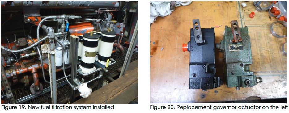
The baring tool was removed and the starter motors installed before the coolant preheaters energised. The existing fuel filtration system required updating, this was assembled and installed with new filter body, spin-on filter cartridges, piping and valves.
The governor actuator had been seen to require assistance during start-up procedures during a previous visit, this was therefore replaced with a new unit.

Outcome
Testing
The engine coolant system was allowed to heat to 42°C and the pre-lubrication system run overnight to ensure lubrication oil reached all internal areas. The low-pressure fuel system was bled up to the fuel injection pumps and all isolations removed. The battery system was allowed time to recharge the batteries.
The engine start sequence was initiated and the engine cranked, but only managed 55rpm. The minimum requirement for the governor to initiate the fuel actuator is approximately 120 rpm, therefore the engine was unable to attempt a start. The fault was traced to unserviceable batteries, an attempt to recharge these was conducted but this failed to provide the required rpm to initiate a start.
Outstanding Actions
Once replacement batteries are sourced the engine will require an initial 10 minute ‘no load’ run to confirm the engine is leak-free. A minimum of 4 hours ‘on load’ test is then to be conducted to confirm the engine is performing within the manufacturers’ specifications. It is recommended that the testing of the engine be carried out under controlled conditions and therefore we would recommend that Bartech re-attend the platform to complete the engine commissioning.
New inlet and exhaust valves on this type of engine bed in very quickly. It is recommended that the valve clearances are checked after the test run to confirm the correct clearances are maintained.
Recommendations
As the overhaul conducted was only a ‘top-end’ overhaul it is recommended that the outstanding actions not completed during the previous Bartech visit are performed.
Bartech was invited to investigate why the coolant on Emergency Generator ‘B’ was emptying from the header tank during start-up and then reappearing on shut
down. It was found that large quantities of air were trapped in the cooling system and required bleeding. This design of engine is prone to developing airlocks if filled
too quickly. We recommend filling the coolant system from the crankcase coolant jacket drain point while having the bleed valves and header cap open. This will
gently push any air out during filling and prevent airlocks.
The standard practice for testing both Waukesha emergency generators on this platform is to allow them to run for 1 hour ‘off load’. This will have a detrimental effect on these engines as the manufacturer recommends that the engines should be run for no more than 10 minutes ‘off load’ in order to prolong engine life. This is due to the lack of intake air (turbos not fully engaged), the pistons not reaching normal operating temperature and therefore not providing an adequate gas seal and the exhaust temperatures being too low. This, in turn, leads to excessive carbonisation, glazing of the cylinder bores and ‘wet stacking’ of the exhaust system. It is our recommendation that the test runs be conducted ‘on load’.
It is recommended that Emergency Generator ‘B’ is fitted with the same updated fuel system as this will aid fuel filter changes and reliability.
Additional Tasks
Bartech was invited to conduct some additional work to Emergency Generator ‘B’ engine.
This included the following:
Changing of fuel filters
Bleeding of the air from the coolant system
Starting of the engine and carrying out a test run for 10 minutes ‘off load’
The above work is in no way a substitute for the need to carry out a full service which should be carried out in line with the manufacturers’ guidelines and recommendations.
Got a problem like this that you need help with? See how we can help!
Find out moreYou might also find these case studies interesting...
-
Case study
Twiflex clutch repair and refurbishment
Find out more -
Case study
Detroit 8V-71 BMSN1496 Fully dismantle, clean and inspect the torque converter
Find out more -
Case study
Investigate oil leak at turbine end of the Holset 4MF turbocharger on a coolant engine
Find out more
If you’re after a trustworthy engine specialist with an excellent track record for your job then let's get started
Get support now 01206 673101 24hProud to be supporting:




Engineer Resource Vol. 2 is now out for FREE download. Get your copy now!
A collection of articles to help you improve engine reliability, performance and safety specifically for engineers, brought to you by Bartech Marine. Simply enter your email below to get instant access.
By completing this form you are agreeing to our privacy policy.
