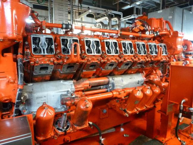
MTU 16V396 Emergency Generator Overhaul
Read more on how we helped this client below and discover how we can help you too...

Background
Bartech was invited by an offshore client to complete an overhaul of the MTU 396 Emergency Generator set B after evidence of cylinder liner scoring was found during a previous borescope inspection. Work would be completed for the most part on a day/night shift basis.

Solution
Dismantle of engine:
To facilitate the removal of the cylinder heads the following components were removed:
Oil and coolant
Exhaust manifold and coolant pipework
High pressure, low pressure fuel pipes and clamps
Rocker covers, injectors and intermediate covers
Rocker gear, pushrods and air start system
Oil coolers and pipework
Cylinder heads
Bearings
Pistons
Cylinder liners
The internal surfaces of the liners were examined and some were found to have broad discolouration lines running from ‘Top Dead Centre (TDC)’ to ‘Bottom Dead Centre’(BDC)and these were approximately 40 mm wide.
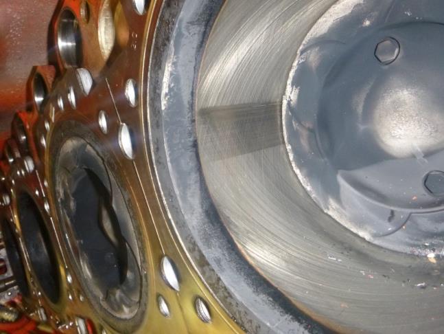
These lines were not deep enough to remove the honing marks but are consistent with marks caused when an injector has been ‘hosing’. This allows unburned diesel to wash away any lubrication oil from the liner surface, causing discolouration and wear to the liner surface.
At this point, the crankcase was thoroughly cleaned to allow the accurate measuring of the internal dimensions. To confirm all tolerances were within the manufacturers
specifications the following measurements were taken:
Crankcase E-bore
Liner internal bore diameter
Conrod big end internal diameter with bearings and torqued to specification
Crankpin diameter
Connecting rod big end measurements
The measurements were all within specification.
New O rings were fitted to the replacement cylinder liners in accordance with the MTU workshop manual and pressed into position. A final internal bore measurement was taken
to confirm correct installation.
During this process, it was noticed that the bottom measurement was outside the OEM recommended tolerance. At this point, conformation was requested from MTU Friedrichshafen that the findings were acceptable.
MTU confirmed that there was a discrepancy in their workshop manual and as a consequence, the liner O rings would require installation in a different orientation. MTU
confirmed that the incorrectly arranged configuration would affect the liners internal diameter. New O rings were ordered and work on the cylinder block was temporarily
suspended. Unfortunately, the pistons had already been installed and the sump raised, therefore, identifying the need to supply and fit a new sump gasket. The pistons required to be removed following the arrival of the replacement O rings.
A sump gasket was subsequently ordered and supplied to the platform.
To confirm that the main journal bearings were in good condition two main bearing caps were removed and the bearing shells inspected. These were found to be in
excellent condition and were reinstalled as per the manufacturer’s specifications.

The turbo cooling shrouds were removed to allow the removal of the turbo and intercooler matrix.
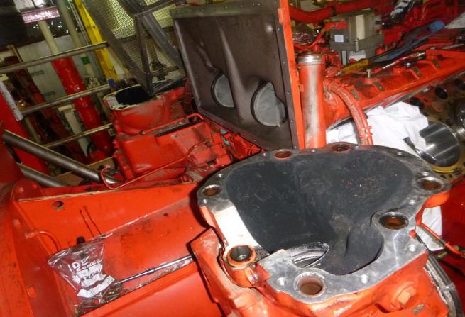
The mating surfaces were cleaned and replacement turbos fitted along with O rings and seals. While the replacement intercooler was being removed from its protective packaging it was noticed that it was in poor condition having been issued from the operator’s supplied stock.
Following discussions with Platform Mechanical Team Leader (MTL) a decision was made to refit the original matrix as this was in a superior condition. The coolant pump was hydraulically removed and the replacement fitted.

The engine was barred over so cylinder A5 was at ‘Top Dead Centre’. The fuel injection pump drives were marked before being removed from the engine saddle.

The drive flanges and gears were removed and fitted to the replacement pumps along with the additional fittings and control rods. The Thermostat valve was removed and a new replacement fitted.
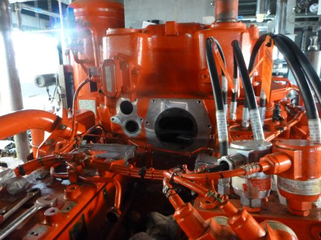
The sea water/coolant heat exchange plates were removed and replaced with reconditioned plates and new bronze bushes installed. There was evidence of erosion to the aluminium endplate, this will have to be monitored to ensure this does not deteriorate and it might be prudent to attach an earth bonding strip to the engine body to prevent further galvanic corrosion.
Both oil coolers were split in order to replace the internal matrix with replacement items. When the replacements were unpacked for installation it was noticed that they were unfit for use due to foreign debris inside the units, some of which was of a metallic nature. A decision was made to refit the original units as any of this debris released would feed directly to the crankshaft bearings, big end bearings and turbos.
Cleaning
All components removed from the engine were cleaned to remove old gaskets, O rings, dirt and deposits.
This included the following:
Exhaust system
Cylinder block
Sump
All coolant and oil pipework
Engine saddle
Oil coolers
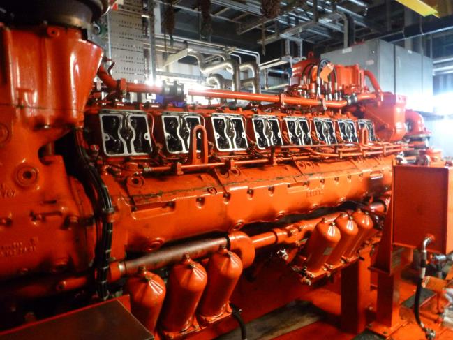
Outcome
Rebuild
The engine was set to the point of injection at A5 cylinder (15 degrees before TDC) and No. 1 fuel injection pump set and installed into the engine saddle.
Timing was set and the pump torqued into position and the engine turned through 720 degrees to confirm correct timing. Cylinder A1 was set to 15 degrees BTDC and No.2 fuel injection pump installed.
The driveshaft was connected and torqued before the pump timing was set.

The engine was rotated again through 720 degrees to confirm correct timing.
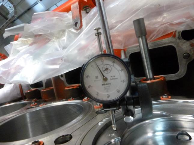
Once the replacement cylinder liner O rings arrived the pistons and liners were removed, cleaned and O rings fitted in the correct orientation. The liners were then reinstalled into the crankcase with the use of the installation tool.
To confirm that the liner bores were within specification the internal dimensions were measured and all were within tolerance.
The liner protrusion was measured and cross-referenced with MTU specifications and confirmed to be within tolerance.
The new pistons, big end bearings and caps were refitted and torqued to MTU specifications. Free movement of con rods was checked and the engine turned through 720 degrees to confirm the free movement of the pistons.
The bump clearance of each piston was measured and confirmed to be within MTU specifications and that the correct thickness of cylinder head gasket was being installed.
A new gasket was installed on the sump then raised into position. The cylinder heads were installed and torqued down as per the manufacturer’s specifications allowing the following components to be fitted:
Rocker gear
Pushrods
Valve clearance adjusted
Intermediate covers
Injectors
Low-pressure fuel pipes
High-pressure pipes
Fuel filters changed
Air filters changed
Crank breather changed
Replacement oil filters
The oil coolers were lifted into position and pipework connected using new O- rings and seals. The exhaust systems were refitted and torqued into position utilising new seals
throughout.
- Exhaust system installed
- Oil coolers in position
Pressure Testing
The coolant system was filled with freshwater and pressurised using a hand pump, during this process a leak was discovered at B8 cylinder head and B bank exhaust.
These leaks were rectified by readjusting the O rings and the test conducted again. A pressure of 0.5 bar was applied (maximum working pressure) and held for 1 hour. No pressure loss or leaks were identified confirming the integrity of the cooling system.
The sump was filled with lubrication oil and the fuel system bled. The isolations were removed and the coolant pre-heater allowed to reach 50 degrees C. The following
starting procedure was followed:
Governor linkage removed and the engine started and held manually at 700 rpm for 1 minute. The engine was then stopped. Emergency shut off flaps were also tested to confirm correct operation.
The rocker covers were removed and a visual inspection was conducted to make sure that lubrication oil had reached all the rocker gears. The rocker covers were refitted.
The engine was restarted and held manually at 700 rpm for 10 minutes. Visual checks were conducted to confirm there was no oil, fuel or coolant leaks. The engine was then stopped.
Governor linkage was reconnected and a full-speed ‘no load’ start conducted.
During this start procedure, the engine initially started then shut down. Further starts were attempted but the engine would not respond.
Following an examination, it was found that fuel was entering the fuel pumps but no fuel was being pumped into the high-pressure circuit.
It was decided to remove the fuel pumps and reinstate the original pumps.
To facilitate the removal of the fuel pumps it was necessary to remove the following from the engine:
High-pressure fuel lines
Low-pressure fuel lines
A1 and A5 injectors
Pumps
Drive flanges and drive gears. (refitted to original pumps)
Fittings, plates and covers (refitted to original pumps)
The original fuel pumps were reinstalled and timed to the relevant cylinders. All injectors, pipes and clamps were fitted and the fuel system bled.
Testing
The engine was started on no load for 20 minutes to confirm correct operation; the load was then gradually increased as follows:
25% rig maximum load (0.5 Mw) for 20 minutes
50% rig maximum rig load (1.0 Mw) for 20 minutes
75% rig maximum load (1.5 Mw) for 3 hours
The load was gently decreased to ‘no load’ over a ten minute period and the engine allowed to cool down before being stopped. The test run ran for a total of four hours, all
temperatures and pressures can be seen on the ‘Test Sheets’ attached to this report.
Conclusions and summary of key issues found during engine overhaul
During the overhaul, a number of issues were identified, many of which added nonproductive time to the programme below is a summary of those key issues:
Spares
Prior to mobilisation Bartech offered to inspect, test, label and categorise all spare parts held by the operator as stock, prior to the commencement of the work scope, in our Colchester premises. Unfortunately this did not happen.
Our engineers used two twelve-hour shifts identifying and sourcing from the large number of spares held on the platform those required for the overhaul. The spares provided to our engineers whilst on the platform were unfortunately not able to be provided in a logical or methodical manner.
The condition of a number of the spares were in a poor or ‘used’ state. Two days were used for inspection, rebuilding and replacement of spares in a concerted effort to maintain the programme.
Cylinder liner O rings
Due to a discrepancy in the MTU manual, the liner O rings were incorrectly installed. This had a detrimental effect on the internal dimensions of the newly installed liners and had to be removed and new O rings installed (Figure 19). This stopped the rebuilding of the cylinder heads but did not prolong the programme as the workscope was rearranged so as not to delay the programme. In this case, alternative productive work was completed further down the workscope which included the removal of the turbos, intercooler and fuel pumps whilst waiting for the replacement O rings to arrive.
A permanent record of the error in the MTU handbook has been noted in Bartech technical library to prevent this error occurring in the future. Noting this to be a technical error, replacement O rings were provided at no charge to the operator.
Intercooler
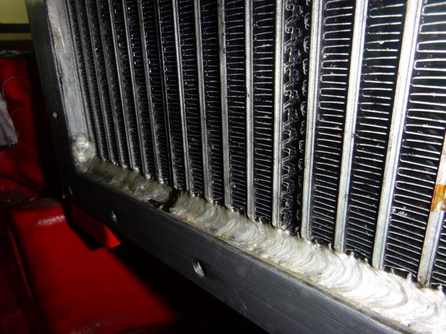
Following the removal of the protective packaging from the platform supplied replacement intercooler it was noticed that it was a reconditioned spare. A closer inspection found that a large amount of oil residue was present and debris was found in the cooling fins.
Due to the fact that the fins would require cleaning and the origin of the intercooler was unknown to us (not known if a pressure test had been completed). It was decided
following discussions between the Bartech engineers and the MTL that the risk to the engine was too great and the original intercooler matrix was to be reinstalled.
Oil coolers
Once the oil cooler internal heat exchange elements had been removed from their protective packaging it was noticed that they both seemed dirty.
The external surfaces were cleaned and clean diesel used to flush out the internals. While conducting this, large quantities of foreign material was evident, some of the debris looked to be metallic in composition and was consistent with what would be expected to be found from a component removed from a failed engine.
Two further attempts to flush the units were attempted, but debris was evident after each attempt.
The decision was made not to fit these items as any debris released would enter the oil supply to the main bearings, big end bearings, turbos and piston heads. The original
items were subsequently refitted to the engine.
Fuel injection pumps
After installing the new fuel injection pumps, the engine was held at 700 rpm for a ten minute period with no fault found. Once the engine was allowed to run to 1800 rpm it
stopped.
The engine would not restart and had all the symptoms of receiving no fuel. The fuel lines, non-return valves and return lines were checked and confirmed as working. The constant pressure valves on each fuel pump were loosened, but no fuel was present when the engine was cranked.
The decision was made to remove the fuel pumps and reinstall the original pumps.
During the removal of the new pumps, it was noticed that the timing marks used to originally align the pumps were out by approximately 60 degrees.

When the new pumps were running at 700 rpm the fuel rack indicator was reading 3. With the original pumps installed and the engine running at 1800 rpm the indicator read 2.
It is our hypothesis that only one of the new pumps was working (hence the higher reading for lower rpm) and when the engine revs were increased, a partial seizure occurred in the offending pump causing the drive gear to slip. This will not be proven until both pumps are sent for testing.
Point to note: During the initial installation of the reconditioned fuel pump (pump No. 2), it was noticed that damage had occurred to the rear of the pump.
This damage was consistent with that of a dropped pump as the actuator plate had two sheared cap head screws and two bend studs. These damaged items were replaced before timing was conducted.
Recommendations
Earthing bond to be fitted to the seawater/coolant heat exchange endplate. This will help prevent galvanic corrosion.
Return fuel injection pumps for survey and inspection
Operator supplied spares to be inspected in the future prior to any mobilisation to reduce downtime and prevent programme extension.
Following discussions with the operator it was agreed that major/minor and overhaul kits would be procured and stored at Bartech premises for future engine interventions.
Got a problem like this that you need help with? See how we can help!
Find out moreYou might also find these case studies interesting...
-
Case study
Twiflex clutch repair and refurbishment
Find out more -
Case study
Detroit 8V-71 BMSN1496 Fully dismantle, clean and inspect the torque converter
Find out more -
Case study
Investigate oil leak at turbine end of the Holset 4MF turbocharger on a coolant engine
Find out more
If you’re after a trustworthy engine specialist with an excellent track record for your job then let's get started
Get support now 01206 673101 24hProud to be supporting:




Engineer Resource Vol. 2 is now out for FREE download. Get your copy now!
A collection of articles to help you improve engine reliability, performance and safety specifically for engineers, brought to you by Bartech Marine. Simply enter your email below to get instant access.
By completing this form you are agreeing to our privacy policy.
